AtvsParts

Tell you how to install atv regulator

  1. Disconnect the battery: Before working on the electrical system, disconnect the ATV’s battery to prevent any accidental electrical discharge or short circuits.
  2. Remove the old regulator (if applicable): If you are replacing an existing regulator, use the appropriate tools to disconnect any electrical connectors or wiring attached to the regulator. Remove any retaining bolts or brackets holding the regulator in place.
  3. Install the new regulator: Align the new regulator in the same location where the old regulator was mounted. Use the appropriate tools to secure the regulator in place, ensuring that it is firmly attached to the ATV. Reinstall any retaining bolts or brackets.
  4. Connect the wiring: Connect the electrical wiring to the new regulator. Follow the wiring diagram or instructions provided by the regulator manufacturer to ensure proper connections. Use electrical connectors and heat shrink tubing, if necessary, to secure the connections and protect them from moisture and corrosion.
  5. Reconnect the battery: Once the wiring is connected, reattach the ATV’s battery cables to the appropriate terminals. Ensure that the connections are secure and tight.
  6. Test the regulator: With the battery reconnected, start the ATV’s engine and monitor the voltage output using a multimeter. Verify that the regulator is functioning correctly by ensuring that the voltage output is within the specified range. Consult your ATV’s manual or manufacturer’s instructions for the recommended voltage range.

“Keyword”
“polaris sportsman 500 voltage regulator location”
“polaris sportsman 500 voltage regulator test”
“2007 polaris sportsman 500 voltage regulator location”
“polaris voltage regulator kit instructions”
“2008 polaris sportsman 500 voltage regulator location”
“2004 polaris sportsman 400 voltage regulator location”
“2001 polaris sportsman 500 voltage regulator location”
“2005 polaris sportsman 500 voltage regulator”

Tell you how to install atv mirrors

  1. Determine the mirror placement: Identify the ideal mounting location for the mirrors on your ATV. Common locations include the handlebars, the frame, or the A-pillar.
  2. Prepare the ATV: Park the ATV on a level surface and engage the parking brake. Turn off the engine and remove the key to prevent accidental movement.
  3. Mount the mirrors: Depending on the mirror type, follow these steps:

    a. Handlebar-mounted mirrors: For mirrors that attach to the handlebars, use the provided mounting hardware or clamps. Position the mirror in the desired location on the handlebars, ensuring it doesn’t interfere with your hands or controls. Use the appropriate tools to secure the mirrors firmly.

    b. Frame-mounted mirrors: If the mirrors mount to the ATV’s frame, identify suitable mounting points. Drill pilot holes if necessary, then attach the mirror brackets using the provided hardware. Ensure the mirrors are level and positioned for optimal visibility.

    c. A-pillar-mounted mirrors: Some ATVs have mounting points on the A-pillar (the upright frame near the front fenders). Attach the mirrors to these mounting points using the provided hardware, ensuring a secure fit.

  4. Adjust the mirrors: Once the mirrors are mounted, adjust them to the desired position for optimal rearward visibility. Ensure you can see behind you clearly without obstructing your view of the trail or other obstacles.
  5. Double-check the installation: Give the mirrors a firm shake and tug to ensure they are securely mounted. Test the visibility by sitting on the ATV and checking the mirrors from your riding position.

“Keyword”
“how to install atv tires”
“how to install mirrors on motorcycle”
“how to install atv tires on rims”

Tell you a few problems encountered when installing ATV carburetor

1. Checking the Intake Manifold: Before installing an ATV carburetor, check the intake manifold and the carburetor flange for dirt, debris, and any signs of corrosion or wear. If any of the components are damaged or corroded, then they should be replaced.

2. Installing the Correct Carburetor: It’s important to install the correct carburetor model on an ATV. If the model isn’t the correct one, they won’t fit properly and could cause issues with the engine’s performance. Therefore, it’s important to research what model and size you need before installing the carburetor.

3. Sealing the Intake Manifold: To ensure an airtight seal between the intake manifold and the carburetor flange, a gasket should be used. This gasket should be of the highest quality to ensure it won’t fail over time and cause a vacuum leak.

4. Adjusting the Float Level: After installation, it’s important to adjust the float level. This adjustment is necessary to ensure fuel is delivered to the engine at the correct level. If the float level is set too low, fuel will not be delivered properly and the engine may not run correctly.

5. Setting the Idle Speed: The idle speed can be adjusted either by adjusting the carburetor’s idle mixture screw or with an electronic control unit. This adjustment should be made after the float level is set and the engine is warmed up.

6. Connecting the Fuel Lines: Fuel lines must be securely connected to the carburetor and should be routed in such a way to avoid kinks and bends that could cause fuel starvation. In addition, rubber fuel lines should be checked for cracks or other damage.

“Keyword”
carburetor problems symptoms”
“how to fix carburetor problems”
“what does a bad carburetor sound like”

WHAT ARE THE SYMPTOMS OF A FAILING BRAKE MASTER CYLINDER?

The master cylinder is a vital component of the car’s braking system. This cylinder is the principal valve through which brake fluid is pushed to make the calipers press brake pads on the rotors.

In essence, this means it plays a significant role in making the car stop when you apply brakes. Any problem with the master cylinder can lead to an accident while you are on the road.

Some of the symptoms of master cylinder failure you should be on the lookout for include:

1. Check Engine Light Indicates

The check engine light has sensors that detect any part of the engine that has malfunctioned. When it comes on, you need an expert to diagnose the problem. If the problem is with the master cylinder, take appropriate action as soon as possible.

2. The Brake Pedal Behaves Abnormally

A problem with the brake master cylinder will cause the brake pedal to behave abnormally. All the pressure in the braking system is generated from the master cylinder. If it malfunctions, the cylinder will not distribute pressure properly, and the pedal will be affected.

When you continue using your car will a bad cylinder, it will wear out and start leaking. The pedal will also feel spongy, mushy, and may sink far down when pressed.

3. Brake Fluid Leakage

If you notice any leakage from the brake master cylinder, it may indicate that the cylinder has problems. For the cylinder to work well, it needs an adequate amount of brake fluid to exert enough pressure to stop the car. When the fluid leaks, you’ll find it difficult to stop the vehicle.

4. Brake Fluid Gets Contaminated

If your brake fluid gets contaminated, it would mean that the master cylinder has some problems. There are rubber seals on the master cylinder that wear out and break down with continuous use.

When that happens, the brake fluid will get contaminated. When the seals are damaged, the cylinder will not hold fluid or brake pressure effectively, and this will cause the pedal to be mushy.

About brake master cylinder
“brake master cylinder symptoms”
“brake master cylinder replacement”
“brake master cylinder repair”
“brake master cylinder price”
“brake master cylinder function”
“brake master cylinder motorcycle”

What Does the Voltage Regulator Do for an ATV?

Your voltage regulator turns the alternative current (AC) into a direct current (DC). This ensures that your battery gets just the right amount of power at any time. The majority of this power makes your ATV run properly and without any sputtering.

Should you ride your ATV without a voltage regulator, your battery will become overcharged. This would mean that all of the AC energy is being concentrated on the battery and does not flow to the other components of your ATV that need power.

As your battery continues to handle this much power, it will start to weaken and and eventually die completely. When your voltage regulator starts to have issues, your ATV will not seem as powerful as it should.

However, we all know there are many reasons your ATV can lose power.  Because of that, there are other problems that you should look out for on your ATV that will suggest that your voltage regulator is starting to fail.

About ATV regulator
“atv regulator rectifier for sale”
“chinese atv regulator wiring”
“honda atv regulator rectifier”
“symptoms of a bad atv regulator/rectifier”
“how to test atv regulator”
“chinese 110cc atv regulator”

How an ATV Carburetor Works

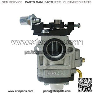
An ATV carburetor performs the vital role of mixing air and gasoline (in the right amounts) before getting the mixture into the ATV’S cylinders. Although not commonly used in modern ATV releases, carburetors are still popular for owners who don’t mind tuning their cars or ATVs frequently. But how does an ATV carburetor work?

An ATV carburetor works by mixing air and fuel to allow for internal combustion. Carburetors usually have a narrow kink called a venturi that speeds up the air, thus lowering its pressure. Decreased air pressure allows the fuel pipe to release fuel, allowing air and fuel to mix in the cylinders.

Curious to learn how an ATV carburetor works? Then you couldn’t be in a better place. Read on as we break down the basic functions of a carburetor.

What Is a Carburetor?

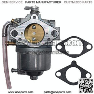
A carburetor is a mechanical device that mixes fuel and air to allow for internal combustion. Its function is inspired by Bernoulli’s principle, which states that as air moves faster, its static pressure reduces, consequently increasing its dynamic pressure.

An ATV carburetor has an open pipe in the form of a venturi, which allows for the passage of air into the engine’s inlet manifold. The inlet manifold, also called the intake manifold, is part of the engine that supplies the air/fuel mixture to the cylinders.

The venturi widens and narrows strategically to regulate airspeed. You’ll find a butterfly valve known as the throttle valve, which can be turned to either block or allow airflow into the system. By controlling the amount of air that flows through the carburetor’s throat, the valve determines the air/fuel mixture ratio, thus regulating engine speed and power.

The narrowest part of the venturi usually has small holes that allow for the introduction of fuel. The presence of jets ensures that fuel flow is regulated precisely in the fuel path, thus allowing for proper combustion.

How Does an ATV Carburetor Work?

Carburetors usually vary in terms of design and complexity. However, most of these mechanical devices function on the same basic principle- mixing air and fuel to promote combustion and consequently power the engine.

You’ll find that most ATV carburetors use a simple design. They have a vertical air pipe that’s strategically located above the engine cylinders. The vertical air pipe is then joined to a horizontal fuel pipe (at the narrowest part of the venturi).

The failing pressure of the speeded-up air creates a much-needed sucking effect for the release of fuel. The air-fuel mixture can then be regulated through two swiveling valves located above and below the carburetor’s venturi.

The top valve is called a choke and regulates the amount of air that can flow in the venturi. When the choke is closed, airflow is restricted, allowing the venturi to suck in more fuel, thus giving the engine a fuel-rich mixture.

This comes in extra handy when the engine is cold, running quite slow, or when it’s just starting up.

The second valve is called the throttle and also helps to regulate the air-fuel mixture. The more the carburetor’s throttle is open, the more the airflow inside the carburetor, which translates to more fuel being sucked.

This results in more energy release, increased power, and eventually a faster ATV, hence explaining why opening the throttle valve allows an engine to accelerate.

Here’s a quick summary of how the ATV carburetor works:

  • Air flows from the ATV’s air intake and into the top of the carburetor.
  • The air then passes through a filter that cleans potential debris, ensuring only clean air gets inside the carburetor.
  • When the ATV engine is started, the choke can be adjusted such that it strategically blocks the top of the pipe, thus reducing the total amount of air flowing inside the carburetor. This consequently increases the fuel content in the mixture that enters the cylinders.
  • In the center of the carburetor, the air is forced down through the venturi, which speeds it up, thus leading to a drop in overall pressure.
  • The dip in air pressure helps create suction on the fuel pipe, which draws in the fuel.
  • The throttle, located at the bottom of the venturi, regulates the mixture of air and gas to allow the engine to produce more power, making the ATV move faster.
  • The air and fuel mixture then flows into the engine’s cylinders.
  • The fuel is continuously supplied to the mixture through the float-feed chamber.
  • The choke opens whenever the fuel level falls.
  • Increased air supply means the pressure will reduce at the venturi, thus allowing for increased fuel flow.

About ATV carburetor
“atv carburetor replacement”
“atv carburetor parts”
“atv carburetor diagram”
“atv carburetor near me”
“atv carburetor cleaner”
“atv carburetor rebuild kit”

How do you test ATV solenoids for performance?

1. Visually inspect the solenoid for any signs of damage or corrosion.

Check the wiring connections to ensure that they are properly secured and not corroded.

Ensure that the solenoid is clean and free of any debris or dirt.

Check the electrical circuit to make sure that it is working properly.

Test the solenoid with a multimeter to make sure it is functioning properly.

If necessary, replace any faulty parts or wires.

2. Connect a multimeter to the solenoid and check the voltage reading. The voltage should be between 8-12V when the solenoid is energized.

If the voltage is too low, it could indicate a problem with the solenoid or the power supply. If the voltage is too high, it could indicate a problem with the circuit or a possible short.


3. Test the continuity of the solenoid by connecting the multimeter to the terminals and checking for a current flow.

To test the continuity of a solenoid, you will need to use an ohmmeter. Connect the multimeter leads to the terminals of the solenoid. The multimeter should display a reading of zero ohms, indicating that the solenoid is continuous and has no breaks in the circuit. If the multimeter displays any other value, then there is a break in the circuit and the solenoid is not continuous.
4. Check the amperage draw of the solenoid by connecting the multimeter in series with the solenoid and reading the current flow.

To check the amperage draw of a solenoid, you need to connect the multimeter in series with the solenoid. Set the multimeter to measure current in amps and then connect the probes from the multimeter to the power and ground terminals of the solenoid. Then, turn on the power to the solenoid and read the current flow on the multimeter display.
5. Test the solenoid’s response time by connecting a timing device to the solenoid and measuring the time it takes for the solenoid to open.

Record the results, and repeat the process several times to ensure accuracy.

About ATV solenoid
“atv solenoid just clicks”
“atv solenoid”
“atv solenoid wiring diagram”
“atv solenoid buzzing”
“atv solenoid clicking but won’t start”
“atv solenoid replacement”

HOW TO BLEED YOUR BRAKES THE STANDARD (MANUAL) WAY

TOOLS AND PARTS NEEDED:

  • A jack
  • A wheel nut tool
  • Small impact driver
  • 8 mm wrench
  • A clamp
  • Brake fluid—you’ll want to double-check the manufacturer’s requirements.
  • A bucket to collect old brake fluid

STEP-BY-STEP

  1. Take your jack and raise your rig so you can get underneath.
  2. Take your wheels off using your wheel nut tool and set them to the side.
  3. Locate and remove the brake fluid reservoir cap. If you’re having a hard time removing the screws, use your small impact driver by giving it a light tap.
  4. Clean the cap and rubber diaphragm thoroughly.
  5. Top the brake fluid up to the maximum level mark.
  6. Pump the brake lever or foot pedal 3 to 4 times. Use your clamp to help you keep the brake under tension.
  7. Open the bleeder valve using your 8 mm wrench and let the brake fluid drain into your bucket.
  8. Close the bleeder valve when the brake lever or foot pedal reaches about 80% of its overall travel.
  9. Repeat step 7 and 8 until the brake fluid that comes from the bleeder is completely free of air bubbles.
  10. Do steps 1-9 again on all four wheels.
  11. Top off the brake fluid reservoir.
  12. Replace the lid and rubber diaphragm.

NEGATIVES OF THE STANDARD METHOD

The master cylinder on a UTV or ATV is much smaller than what you would find on a car. Therefore, bleeding your brakes can be a little trickier. Due to their small size, the amount of fluid that is pushed every time you pump the brake is smaller. There may not be enough fluid to efficiently push the air out before you’d have to start the process all over again.

It’s not a quick process. It can take a while to completely flush the brake system, especially if you’re having trouble getting the air out of the line.

About ATV brakes
“how to bleed chinese atv brakes”
“ebc atv brakes”
“how to bleed atv brakes with a vacuum pump”
“how to bleed rear atv brakes”
“polaris atv brakes not working”

About Replacing Tail Light

As you drive on the roads and highways, your primary goal should be to reach your destination safely and without any incidents. Obeying traffic laws and driving wisely aren’t the only ways to do this. It’s important to keep your vehicle in good shape and make sure it is operating correctly. This is true for something as simple as a tail light. When night falls or bad weather strikes, it won’t be easy for other drivers to see your car if one or both of these lights are out. Replacing tail light bulbs is critical, but it doesn’t have to be difficult.

DON’T PUT IT OFF

Responsibly owning and driving a vehicle requires maintenance and attention to detail. It is easy to forget about issues or put them off until a later date. You shouldn’t drive around too long without a tail light. Not only does this pose a danger for others on the road, but it’s also illegal. You could get cited for this infraction, even on a first instance. Other drivers may rear-end you if they can’t see your car’s tail lights. They may lose control trying to avoid your car once they notice you’re there. Take care of this issue as soon as you can.

THE ISSUES

As you look around, you’ll notice that this isn’t an uncommon problem. Taillights fail frequently for many reasons. The bulb itself may have burned out, as these don’t last forever. There could faulty wiring or a disconnected wire somewhere. Accidents could cause the light to crack or break as well. You may have to replace the light and the light cover in some cases.

WHY DO IT YOURSELF?

Even if you are not the handiest person in the world, this is a task you should be able to handle. You don’t have to be a mechanic or even have experience replacing vehicle bulbs. This is an ideal project for a first-timer. It’ll take you more time to finish this than it would for a professional or someone with more experience. However, you’ll be able to save and learn an important skill.

BE PREPARED

It’s important to know what to expect with any car maintenance or repair job. Fortunately, tail light bulb replacement isn’t difficult and shouldn’t take you more than 45 minutes to an hour to complete. Be aware that newer models may be a little more complicated than older ones, as there will be more wires to disconnect. Make sure you grab a screwdriver, socket wrench and a pair of gloves before starting the replacement process.

About tail light
“tail light bulb”
“tail light replacement”
“tail light car”
“tail light out”
“tail lights led”
“tail light housing”

Checking a clutch cable

A typical clutch cable
A typical cable-operated clutch on a front-engined car. Some cars have hydraulically operated clutches.

The clutch cable has a steel-wire inner core sliding inside an outer sheath. It should last at least two years, but check it at every main service; if it breaks it may do so without warning.

The heavy clutch-pedal pressure needed to work it may conceal any initial stiffness or stickiness in the cable itself. The exposed cable ends are the parts most likely to fray and break, especially at the gearbox end.

To check or replace the cable, support the car on ramps or axle stands and chock the wheels on the ground .

Checking the cable

Disconnect the cable at the gearbox end. It is fixed to the clutch-release lever by nuts which also provide adjustment.

Move the clutch pedal by hand. You should be able to feel whether the cable slides smoothly. If it does not, the cable may be bent at too sharp an angle by being wrongly routed.

Usually there are guides to keep its path smoothly curved. Make sure that the outer sheath is not kinked or crushed: if it is, replace the cable.

If the cable needs grease, apply it to the inner cable at each end and slide it back and forth.

Pay particular attention to the cable on a rear-engined car, where its long route makes it extra prone to damage.

Inspect the exposed ends of the inner core, pulling each end in order to reveal as much as possible. If even one strand is broken, the others will soon follow: replace the cable at once.

If the cable passes all checks, reconnect the gearbox end and adjust the nuts until there is the correct amount of free play.

Finally tighten the locknut.

Replacing the cable

Disconnect the gearbox end first and remove the nuts; then free the inner cable from the pedal.

It may have a loop which fits over a hook at the top of the pedal; pull the cable slack and lift it off.

The cable may end in a fork pivoted on the pedal by a clevis pin. The pin has a head at one end and a washer and a split pin at the other, straighten and pull out the split pin with pliers, then push out the clevis pin. Use a new split pin when refitting.

If there is a ball on the end of the cable which fits through a keyhole-shaped slot in the pedal, pull the cable slack and push it up towards the large end of the keyhole to free the ball.

Unscrew any bolts which hold the outer sheath to the bulkhead. Note the order in which washers, spacers and seals are fitted so that you can replace them correctly. Pull the whole cable out through the engine compartment.

Some rear-engined cars, such as the VW Beetle, have clutch, brake and accelerator pedals on a common shaft. To free the clutch cable for replacement you may have to disturb the other two pedals and linkages .

To reach the clutch end of the cable remove the left rear wheel, supporting the car on an axle stand. Adjustment is generally by turning a wingnut or a domed nut and locknut at the clutch end.

Hold the cable with grips to prevent it turning with the nut while adjusting. Turning clockwise reduces free play at the pedal, which should be between 10 and 25 mm. Make sure the adjuster nut is seated properly in the elliptical hole of the clutch lever arm.

Replacing a VW Beetle cable
When replacing a VW cable, adjust it at the clutch. Pass the threaded end through the lever-arm hole and fit the wingnut. Hold the cable with grips during final adjustment to prevent it turning.

Check all the rubber grommets and seals along the route of the cable, and replace any that are worn or damaged. Some may be supplied with the new cable.

Take the old cable and other parts to be replaced to the parts store. Lay the old and new cables side by side and check that they are the same length and that the fittings are the same.

If the old type has been superseded by an approved but slightly different one, make sure you have any adaptors you need.

Find out whether the new cable has to be greased before fitting. Most modern cables have greaseless non-stick linings.

If you do have to grease the cable, use your finger to poke as much high-melting-point grease as you can into the outer sheath at both ends, and slide the cable back and forth to spread the grease.

About clutch cable
“how to adjust clutch cable”
“harley clutch cable length chart”
“barnett clutch cable”
“venhill clutch cable”
“how to tighten clutch cable”
“broken clutch cable”